Xbox 360 Ring of Light Mod (Phat): LED Swap Guide
This guide explains how to perform an Xbox 360 Ring of Light mod on the original "Phat" console's ROL board. This modification involves swapping the original green LEDs with new colored SMDs to customize your console's power button. We will cover the tools you need, two methods for removing the old lights, and how to install the new ones, including the optional error lights.
Tools and Parts for Your Xbox 360 Ring of Light Mod
Before you begin, you will need a few specific tools and parts for this project:
- A 20-30 Watt Soldering Iron (we use a 30 Watt iron).
- Rosin Core Solder.
- A Soldering Stand (highly recommended for safety).
- Tweezers (these are essential for handling tiny SMDs).
- Five 0603 SMDs in your color choice (or nine if you are also installing error lights).
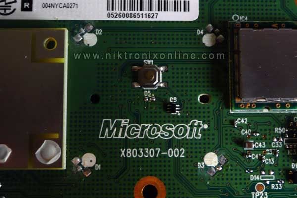
- An Xbox 360 ROL Board (which must be removed from the console first).
- 30 AWG Wire (optional, only for installing the error lights).
- A pair of pliers and wire cutters are also recommended.
- Consult our Polarity Guide if you do not know the positive (+) and negative (-) sides of your 0603 SMD.
Step 1: Removing Old SMDs for the Xbox 360 Ring of Light Mod
First, you need to remove the old LEDs from the ROL board. There are two common methods for removing the four outer SMDs.
Method 1: The "Rocking" Method for ROL Mod
The first method is to take a pair of small pliers and firmly grip one of the larger SMDs. Then, 'rock' the pliers back and forth until the SMD comes off. While this is by far the quicker method, you must be aware that you risk tearing up the solder pad on the circuit board. If you damage a pad, you will face a very difficult repair.
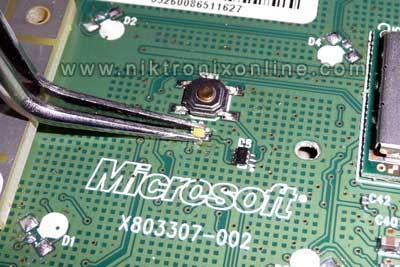
Method 2: The "Floating" Method (Safer)
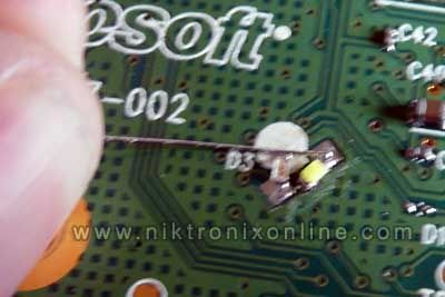
The second, safer method is what we call 'floating' the SMD off. This involves putting a good amount of solder on the tip of your iron. Then, you drag the iron across the back of the SMD where the solder points are. Your goal is to melt all the connections at the same time. If you do this correctly, the SMD will "float off." Do not apply excessive pressure with the iron, as this can also damage the pads. Sometimes, adding fresh solder to each end of the SMD before you start can help it float off more easily.
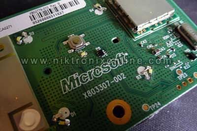
After you remove the four outer lights, you can focus on the middle light. You MUST use the float technique for this middle SMD. If you do not, you will definitely ruin the pads. Take your time and be patient. Once all the lights are off, make sure the solder pads are flat. You do not want mounds of solder sticking up. The board should look like this after you remove the lights:
Step 2: Installing New SMDs for Your Xbox 360 Ring of Light Mod
After you remove all the original lights, you must then install the new ones. This section also uses an important schematic for your **Xbox 360 Ring of Light mod**.
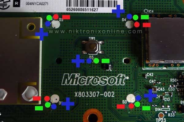
Understanding the Solder Pads
Here is a photo showing which pads are positive and negative. In this image, the primary lights are marked with green, and the secondary error lights are marked with red.
Soldering the Main LEDs for Your Ring of Light Mod
First, let's install the four outer lights. Get out your SMDs, but only remove one at a time from its packaging to avoid losing them. When you have one, use tweezers to pick it up and identify the positive side using our polarity guide. Now that you know the orientation, position it for installation. It should be lying flat with the lens facing directly up. We will solder the positive side first, so add a little solder to the positive (+) pad on the board. Grab the negative side of the SMD with tweezers and hold it just in front of the positive pad. Once it is in position, hold it tightly, melt the solder on the pad, and push the SMD into the solder. After you remove the iron, let the solder cool and harden. Remember to only apply heat for a few seconds at a time to avoid damage. Repeat this process for all four corners.
Next, we will solder the middle light. This one is fairly simple. Make sure the two pads in the middle are flat, without mounds of solder. Then, pick up your fifth SMD, find the correct orientation, and hold it on the pads with your tweezers. Heat the solder on one pad so the SMD sticks, then solder the other side. Your board should now look something like this:

Step 3 (Optional): Installing Error Lights for Your Xbox 360 Ring of Light Mod
If you want to add the red error lights to your **Xbox 360 Ring of Light mod**, continue here. Otherwise, you can install and test your board.
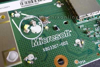
The error lights are not too difficult, but there is a slight trick. You must solder the negative side of the new SMD to the *secondary* negative pad on the outer lights. If you have done it right so far, this will be the pad you have not soldered to yet out of the three. Once you have the negative side soldered, it will look like this:
After you have soldered the ground connection, you must apply power. The power comes from the blue dot in the schematic image viewed earlier. Take a strip of 30 AWG wire and tin it with solder. Then, hold the wire so it touches the positive pad and the positive side of the error light SMD. Melt the solder on the pad to tack the wire down.
Once the wire is tacked down, trim it with wire cutters. Then, solder the other end to the positive part of your error light. Do this whole process for each error light. After that, you are done!
Conclusion on Your Xbox 360 Ring of Light Mod
In conclusion, you are now ready to test your new custom piece. A completed board with all LEDs installed will look like this:
This **Xbox 360 Ring of Light mod** is a fantastic way to personalize your console. Enjoy your new custom ROL! (Credit for photos goes to mmmonkey).